Publikációk
ARDUINO
Fm szintetizátor Arduino Due-val.(magyar nyelv)
Fm synthesizer with Arduino Due. (in English)
Polyphonic Fm synthesizer with Arduino Due
Project description
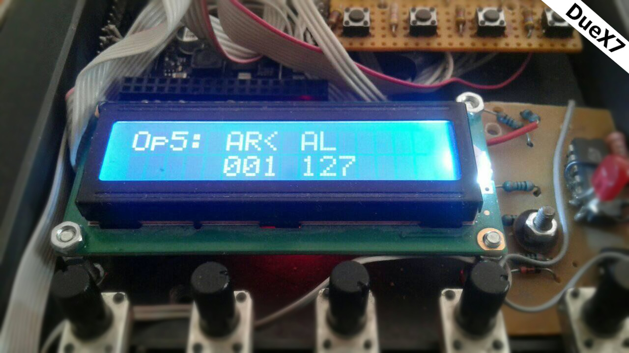
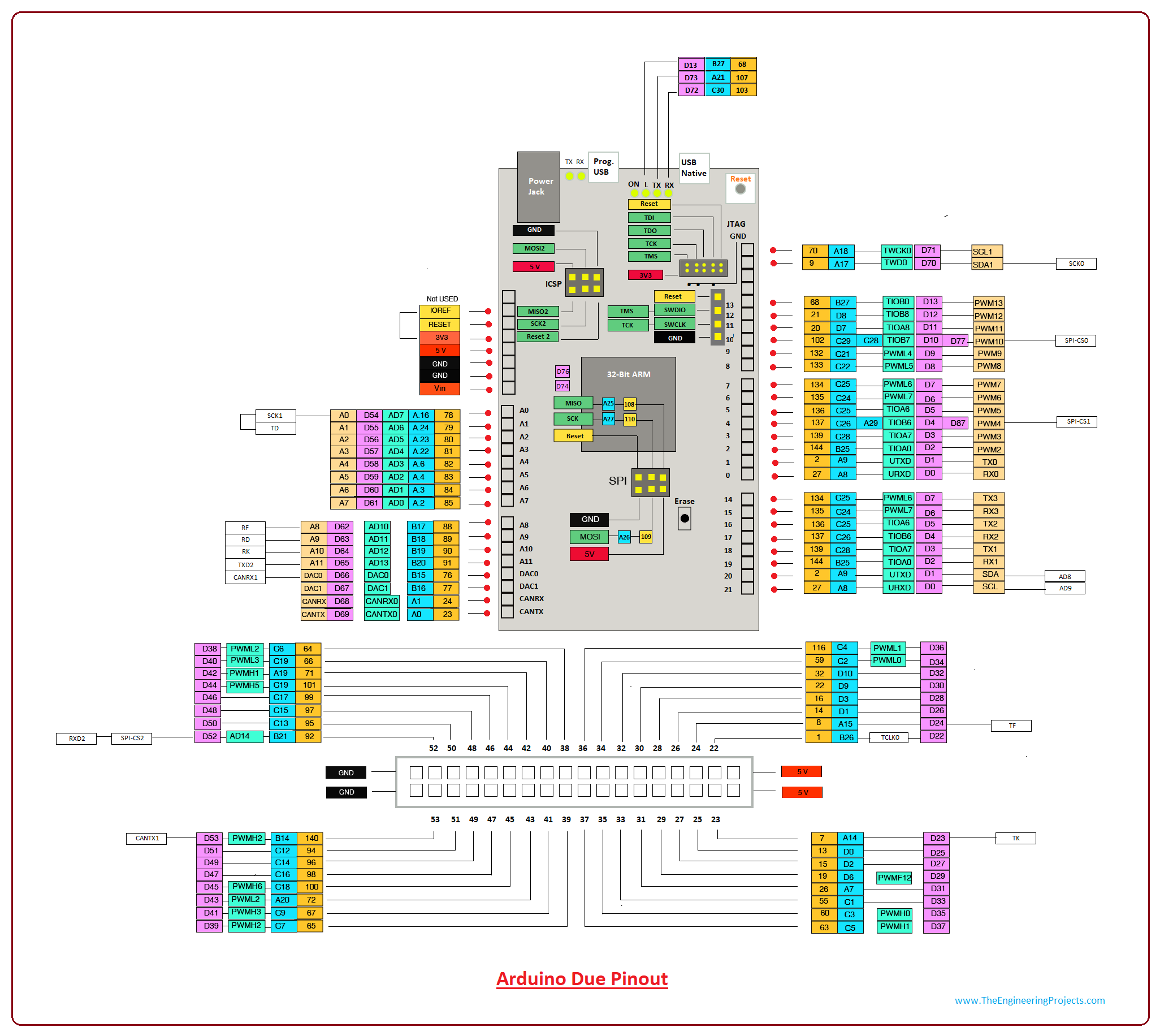
Arduino Due has two 12-bit DACs (with digital-to-analog converters). We take advantage of this, to get audio output. Running program calculates the audio values in a 1024-element buffer in time and then writes them to the output with the functions of the audio.h class. The sampling frequency is 44100Hz. Audio.h handles the signal on 16 bits, while the Arduino Due DAC is only 12 bits. With built-in functions, a sine signal representation is not feasible because it requires a lot of fractional operations, I basically avoid using fractional numbers during the project. Calculates sine and other waveforms into an array the device at startup. Six generators are available to produce one sound. A tone can use 6 operators. (2xone carrier + 2 modulators for fm modulation) For example, op1 and op4 are the carrier. Op2, op3 is op1 modulator, op5, op6 modulator op4. All six generators have variable waveforms, I am still experimenting with their waveforms. Expected development in the near future in mixed mode: thus, three operators are responsible for fm modulation, or three basic waveforms real set (sine, square, triangle, saw). The frequency of the generators can be fixed or depends on the key pressed. Each operator has its own envelope. Their parameters are AR, AL, D1L, D1R, D2L, D2R, RL, RR as usual from Yamaha DX instruments. The actual length of a tone is given by the sum of the AR + D1R + D2R + RR values of the op1 generator. If this time has elapsed, then the tone is considered run. The values of the other operators are valid within this period. In addition, a pich curve is available, the value of which is added with a +, 0, or - sign per operator. to their frequency. The device is dynamically sensitive, the volume of the oscillators may vary in proportion to the dynamics. The finished signal can be written to the output in stereo or mono mode. Current development is to produce a simple reverb effect. Its signal strength or ReberbTime parameter can be adjusted. The device is polyphonic up to 6 tones! Controllable from a simple midi keyboard or computer, 8 preset tones, i.e. contains prestige.
Videos
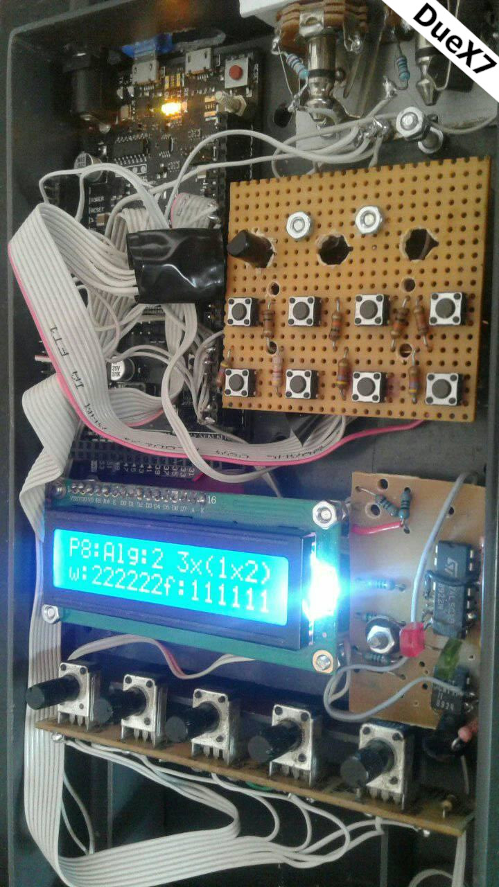
Pictures
Downloadable audio:
Hang1 Hang2 Hang3 Hang4 Hang5 Hang6 Hang7 Hang8 Hang9 Hang10 Hang11 Hang12 Hang13
About the program:
The fm modulation:
The sine signal is generated by shifting the freq pointer by 22 bits, in a 1024-element array preloaded with sine signal values. In this way, the desired frequency can be produced with high accuracy:
buffer=sinusfg[freqmutato1>> 22];
freqmutato1 += sinewave1freq;
It was found in the documentation for a Yamaha YM2151 chip in the implementation of fm modulation was a formula to help me:
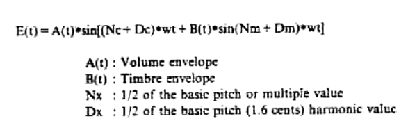
You can see here that the modulation, if the value of B Level is zero, then returns only a simple sine signal. If the volume of the modulator is not zero, then its volume-dependent value is added to or subtracted from the frequency of the carrier, thus modulating its frequency. Of course, in the meantime, the current frequencies of the oscillators must always be monitored, as they can change depending on the pich curve! Producing all of this with a simple sine function would be very easy, but Arduino Due can't calculate it 44100x2 times per second. Therefore, in a 1024-element array, the sine values are computed at start-up and their values are returned according to the frequency.
The soul of Fm modulation with two operators:
sinusfg[((freqmutato1 >> 22) + fmsinusfg[freqmutato2 >> 22] * op2gorbelevel / op2level) % 1024] * op1gorbelevel / op1level
Fm modulation with three operators:
generator1[((freqmutato1 >> 22) + generator2[((freqmutato2 >> 22)+generator3[freqmutato3 >> 22]* op3level/4096)% 1024] * op2level/4096) % 1024] *op1level>>12
Fm modulation with four operators:
generator1[((freqmutato1 >> 22) + generator2[((freqmutato2 >> 22)+generator3[((freqmutato3 >> 22)+generator4[freqmutato4 >> 22]*op4level/4096)%FG_SIZE ] * op3level/4096)% FG_SIZE ] * op2level/4096) % FG_SIZE ] *op1level>>12
These algorithms are the souls of the synthesizer. Their speed is key. Unfortunately, I couldn’t miss the residual division because then sooner or later there was an overindexing in the arrays and the instrument stopped. Or I didn’t have much of an idea to implement feedback, FeedBack. Due to the elimination of the latter, not only sine signals, but also triangular, square and sawtooth signals can be used, both as carriers and modulators, so more complex waveforms can be produced. If you have any ideas for optimizing modulation functions, feel free to write! The implementation of a PWM synthesis-based algorithm, which has arisen in further developments, still exists only in principle.
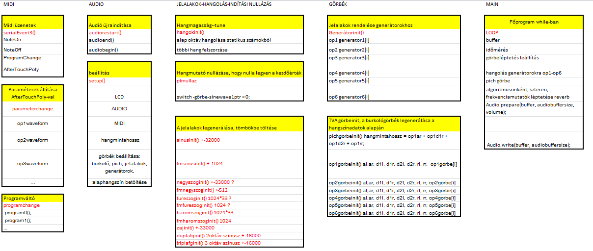
The structure of the program is illustrated in the following figure:
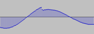
The audio signal is generated in the buffer of the Audio.h library. It still needs to be resolved at the moment due to volume increases extreme curve transition. These harmonics are unfortunately heard at the output. This problem is shown in the figure below. Otherwise, it can be reduced by averaging or adjusting the parameter of the TV curve accordingly.
The compiled buffer is written to the DAC with the following functions.
Audio.prepare(buffer, audiobuffersize, volume);
Audio.write(buffer, audiobuffersize);
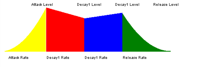
The envelopes
Generate tva envelopes as soon as the tone is loaded, or any tv curve after setting its parameter. Generates an array from the values of the envelope (Attack, Decay, Decay2, Released) whose values contain the volume values according to the curve resolution. The lowest resolution is 2 steps. The current curve time is stored in the gorbetime [0] variable. This value shows where we are in the Tva curve of the sound corresponding to the given key. The curves are shifted by buffer periods. If the key is pressed, the scrolling goes to gorbetime [0]! = Maxrelease0 - 1. In case of release, for the NoteOff parameter for the given sound, gorbetime [0] = maxrelease0 will change to the released state, which goes to maxtime0, then the value of gorbetime [0] changes to -1. This indicates that the process is complete, the curve is in the default state. It also follows that a sound of a given pitch can only sound once at a time. For me, it was absolutely not confusing, it even gives a distinctly lifelike sound, and so I avoided controlling polyphony with more complicated calculations. Since a sound has 6 operators, the appropriate modulation level must be set for each curve step! The "/ op1veloc" division can be used to adjust the velocity parameter, which made the presentation mode so vivid for the first experiment that I didn't even vary it with it. It is also natural that since we are talking about FM modulation, there is no need for a TVF wrapper here. After all, the role of the curve is determined by the algorithm, depending on whether it is acting as a carrier or a modulator, the given operator. The following code shows an example of how to implement the TVA curve step:
if (gorbetime[0] == maxtime0) {
gorbetime[0] = -1;
} else {
if (gorbetime[0] >= 0) {
if (gorbetime[0] == 0) {
ptrnullaz(0);
}
if (gorbetime[0] != maxrelease0 - 1)
gorbetime[0]++;
op1level[0] = op1gorbe[gorbetime[0]] * op1volume * (waveveloc[0] / op1veloc);
op2level[0] = op2gorbe[gorbetime[0]] * op2volume * (waveveloc[0] / op2veloc);
op3level[0] = op3gorbe[gorbetime[0]] * op3volume * (waveveloc[0] / op3veloc);
op4level[0] = op4gorbe[gorbetime[0]] * op4volume * (waveveloc[0] / op4veloc);
op5level[0] = op5gorbe[gorbetime[0]] * op5volume * (waveveloc[0] / op5veloc);
op6level[0] = op6gorbe[gorbetime[0]] * op6volume * (waveveloc[0] / op6veloc);
}
}
if (op1ar > 1) {
for (int i = 0; i <= op1ar; i++)
{
op1gorbe[i] = op1al / op1ar * i;
}
}
else {
op1gorbe[0] = op1al;
}
for (int i = 1; i <= op1d1r; i++)
{
op1gorbe[op1ar + i] = (op1al - (op1al - op1d1l) * i / op1d1r);
}
for (int i = 0; i <= op1d2r; i++)
{
op1gorbe[op1ar + op1d1r + i] = (op1d1l - (op1d1l - op1d2l) * i / op1d2r);
}
for (int i = 0; i <= op1rr; i++)
{
op1gorbe[op1ar + op1d1r + op1d2r + i] = (op1d2l - (op1d2l - op1rl) * i / op1rr);
}
To move or stop the TVs when the sound has ended:
if ((gorbetime[0] >= 0) && (gorbetime[0] < hangmintahossz)) {
if (gorbetime[0] == 0) {
ptrnullaz(0);
}
if (gorbetime0lehet) {
if(gorbetime[0]!=releasetime-1)
gorbetime[0]++;
op1level[0] = op1gorbe[gorbetime[0]] * op1volume * (wave0veloc / op1veloc);
op2level[0] = op2gorbe[gorbetime[0]] * op2volume * (wave0veloc / op2veloc);
op3level[0] = op3gorbe[gorbetime[0]] * op3volume * (wave0veloc / op3veloc);
op4level[0] = op4gorbe[gorbetime[0]] * op4volume * (wave0veloc / op4veloc);
op5level[0] = op5gorbe[gorbetime[0]] * op5volume * (wave0veloc / op5veloc);
op6level[0] = op6gorbe[gorbetime[0]] * op6volume * (wave0veloc / op6veloc);
} else {
gorbetime0lehet = true;
}
} else {
gorbetime[0] = -1;
}
A reverb:
The reverb engine:
bufferbe=(level-2)*bufferbe/level;
bufferbe += delaybuffer[delaybufferindex];
buffer[ bufferindex] = bufferbe;
delaybuffer[delaybufferindex] = (reverblevel-1)*bufferbe/reverblevel;
delaybufferindex++;
if (delaybufferindex > reverbtime) {
delaybufferindex = 0;
}
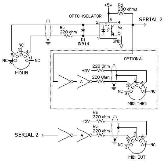
A MIDI:
Processing MIDI events: When a midi event arrives, I process it according to its type. If NOTE-On happened, then the first data byte is the key code, the second is the dynamics value. You have entered 6 generators for the incoming keystroke. because of polyphobia. If we keep it single, the frequency of the first generator (wavefreq1) takes over the and wave0veloc is the value of the dynamics. In addition, I have to reset the tva curve of the given sound generator, to play the sound from the front. Because I have to keep track of which sounds are pressed so the resulting key value I store it in the variable oldnoteByte1. I use this in the Note-off branch for releases. Here are the tva curves for the release (decay) I set a date. In the case of a program change message, I call the program change procedure, which calls for the appropriate tone, or My parameter setting procedure for the AfterTouchPoly message, as the device communicates in real time.
void serialEvent3() {
if (MIDI2.read()) {
if (MIDI2.getChannel() == midichan) {
switch (MIDI2.getType())
{
case midi::NoteOn:
noteByte = MIDI2.getData1();
velocityByte = MIDI2.getData2();
gorbetime[generatornumber] = 0;
wavefreq[generatornumber] = noteertek[noteByte];
waveveloc[generatornumber] = velocityByte;
oldnoteByte[generatornumber] = noteByte;
generatornumber++;
if (generatornumber == 6) {
generatornumber = 0;
}
break;
case midi::NoteOff:
noteByte = MIDI2.getData1();
// velocityByte = MIDI2.getData2();
if (noteByte == oldnoteByte[0]) {
gorbetime[0] = maxrelease0;
}
if (noteByte == oldnoteByte[1]) {
gorbetime[1] = maxrelease1;
}
if (noteByte == oldnoteByte[2]) {
gorbetime[2] = maxrelease2;
}
if (noteByte == oldnoteByte[3]) {
gorbetime[3] = maxrelease3;
}
if (noteByte == oldnoteByte[4]) {
gorbetime[4] = maxrelease4;
}
if (noteByte == oldnoteByte[5]) {
gorbetime[5] = maxrelease5;
}
break;
case midi:: ProgramChange:
noteByte = MIDI2.getData1();
velocityByte = MIDI2.getData2();
programchange(noteByte);
break;
case midi:: AfterTouchPoly:
noteByte = MIDI2.getData1();
velocityByte = MIDI2.getData2();
parameterchange(noteByte, velocityByte);
break;
case midi:: ControlChange:
noteByte = MIDI2.getData1();
velocityByte = MIDI2.getData2();
pichband(noteByte, velocityByte);
break;
case midi:: Clock:
sendmidiclock();
break;
}
}
}
}
During the development, the use of arrays for parameters was a fundamental problem, because the use of array indexing has slowed the loop. That is why there are many parameters separate name created. The names are not minidg consistent either, because many times Numbering starts from 0, often from 1. I can still fix this later. The built-in functions and loops proved to be equally avoidable. So it cannot be used in real time neither the sin nor the rand functions. The tool basically works in a while (true) {} loop. The traversing of the tva curves is synchronized with the millis () function. Unfortunately, when you step, you may hear a crackle if you suddenly step up the volume curve, but this has already been mentioned above. word, correction in progress. By default, the device can receive Note-On, Note-Off, Program Change parameters. And to edit the tone polyphony uses aftertouch messages. Here, the transmitted key code gives the parameter and the value of the next byte gives the value for the parameter.
List and values of adjustable parameters:
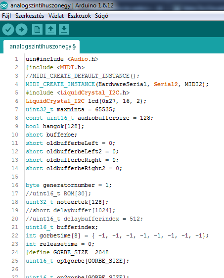
Source code for the alpha version of the synthesizer:
A szintetizátorunkat midi utasításokkal pc-ről is vezérelhetjük:
I started from the following program:
C# MIDI
toolkit
With this program you can save or transfer the current tone, on the other hand
it is expected that the control of the parameters and the display will be solved with an Arduino Nano at a later date.
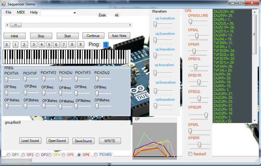
The alpha version of the PC software can be downloaded:
Thank:
I definitely thank the Arduino members of the Hobby Electronics Forum: kapu48 and Benjami for their help! To my family members or neighbors that they have withstood everyday noises, especially if they are saturated due to an incorrect parameter value. I cut the buffer values. And to everyone who left to work. Good luck testing!
Contact:
Az utolsó módosítás: 2023 September 19 13:49:18.